In the last blog post I described the project I've been working on: generating hex grid code libraries, for lots of different types of hex grids. I wanted to transform "proto-algorithms" into algorithms for a specific type of hex grid, and then convert the algorithm into code.. That was the pattern I initially expected to follow, so I'd end up with maybe 50 algorithms multiplied by 70 grid types multiplied by 20 languages, or a total of 70,000 code snippets.
I tried experimenting with other hex grid algorithms to see how they might transform depending on geometry, and realized that most of them don't work like the hex distance example in the previous blog post. I spent some time looking at all the algorithms to determine:
- Do I want to transform the code handling cube coordinates into code handling each other coordinate system? Code to code transforms are hard.
- Do I want to transform the data for other coordinate systems into data for cube coordinates, then run an algorithm for cube coordinates? Data to data transforms are easy.
- Does it even make sense to run the algorithm in a non-canonical coordinate system? Many of the algorithms are best with with cube coordinates.
- Does the algorithm work purely on the grid system, or does it also involve how the hex is drawn on the screen? Most of the algorithms do not involve the screen layout.
I concluded that I had vastly overestimated the number of different algorithms that need to be generated. Many of the variants end up being exactly the same code. For example, I wanted to generate variants for people who have a y-axis pointing up vs down, but only two of the algorithms have to change; all the others can stay the same. Also, it is a lot of work for me to transform the code handling cube coordinates into code handling other systems, but a compiler's optimizer can do all that work for me for free if I use data-to-data transforms. I shouldn't bother writing code-to-code transforms.
While trying to figure out the best way to write the variants, I ended up with this structure:
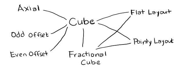
- Cube
- is the canonical coordinate system used for algorithms. I've implemented only one of many variants.
- FractionalCube
- is used to represent non-grid locations. I needed this for line drawing and for pixel to hex conversion.
- Hex
- is the coordinate system used for storage. I've implemented Axial (only one variant) and Offset (even and odd parity).
- Layout
- is used to convert from hexes to screen coordinates for drawing and from screen coordinates to hexes for mouse clicks. I've implemented Pointy and Flat topped hex layouts.
- Point
- is the coordinate system for screen coordinates. This will typically come from your graphics library, but for the generated code I've included a placeholder data structure.
To implement these, I wanted a language that lets me work easily with abstract syntax trees. My usual choices are PLT Scheme (Racket) or ML (OCaml). Scheme is a little nicer for this because it gives me an easy way to define the proto-algorithms using macros so that I don't have to write my own parser. For this particular project though I wanted to run the code generator on the server (to generate all variants and run unit tests on the generated code) and in the browser (to generate custom code based on your preferences). I chose Haxe, an ML-influenced language with the programming features I wanted (tagged unions and pattern matching and macros) and also the platform features I wanted (can run on the server but can also generate Javascript to run in the browser). Also, my hex grid code is already written in Haxe, so I was hoping to be able to reuse it for the proto-algorithms.
I wrote code that reads function definitions and outputs code to generate the syntax trees for those definitions. For example, if I write x+3, Haxe will give me something like EBinOp(OpAdd, CIdent("x"), CInt(3)). I want to produce something like Add(Name("x"), Int(3)), so I need the macro to return something like ECall(CIdent("Add"), [ECall(CIdent("Name"), [CString("x")]), ECall(CIdent("Int"), [CInt(3)])]). I have code that reads code and generates code that generates code. Scheme/Racket is an ideal language for that kind of thing.
In the process of implementing the proto-algorithm to algorithm compiler, I made some discoveries and realizations:
- My diagrams are written in Javascript, which doesn't have a separate int and float type, but in many languages I need to distinguish these. As a result, I created a type
FractionalCubewith floats that's separate fromCubewith ints.FractionalCubeis used for two main algorithms, pixel to hex and line drawing, and both of those need a helper routine, hex rounding. - I realized that my explanation for pointy vs flat top hexagons is inconsistent. In one section, I claim it's a rotation of 30°. In other sections, I claim the algorithms are simply different. In my underlying code, I often swap x and y. The code is simplest if swapping x and y, or rotating 90°, but the names of axes stay most consistent (q for columns, r for rows) if I rotate by 30°. I don't know which I should use.
- It's also possible to generalize even further, and rotate by any angle. This is less "simple" because it means I need to insert an additional rotation step in a few places, but it's more general. I'm not yet ready to switch to this.
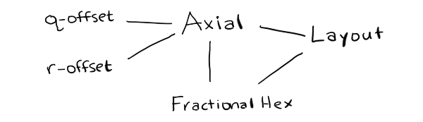
- In the offset grid section, I claim that there are four types, odd-r, even-r, odd-q, and even-q. However, if pointy vs flat is a swapping of x and y (instead of a rotation by 30°), then odd-r and odd-q are related by swapping both x/y and q/r. Much simpler! This means there are really only two offset types, odd-parity and even-parity.
- It's also possible to generalize even further, and say that the offset can be by any odd number. The odd-parity (odd-r and odd-q) variants become an offset by -1 and the even-parity (even-r and even-q) variants become an offset by +1. This simplifies even more. I'm not yet ready to switch to this.
- The remaining grid variants involve renaming the axes and changing their signs. I'd like to implement this at some point, but I don't know if it's really worth it.
- Cube and Axial coordinate systems are pretty much the same, except Cube explicitly stores the third coordinate, and Axial calculates it when needed. It might make sense to merge the two, and call the axes q, r, s. I need to think about this more.
- Offset and Axial share much less code than I had expected. One of the algorithms (
hex_direction) doesn't work with offset grids, and two of the algorithms (hex_neighborandhex_add) have different implementations for offset and axial. If I merge Cube and Axial, then Offset would be its own thing. I need to think about this more. - It's pretty clean to separate out anything involving the screen from everything else, which only involves the grid. This means variants like the y-axis pointing up or down go away, except for a small part of the code. Screen transformations include translations (centering hex 0,0 at x,y other than 0,0), scaling (setting the size of the hex, including hexes that are taller or shorter than usual), rotations (primarily 90° but any angle is possible), and transformations for isometric views.
I started this project thinking I would need to generate lots of algorithms. I thought the algorithm generation step would take the most work, and the code generation step would be relatively easy. I ended up spending a lot more time thinking about how to represent the modules. I don't actually need to generate lots of algorithms. Instead, I am considering changing the page to use a simpler approach:
If I do that, it will be a major change to the hex grid guide.
In the next post I'll talk about the code generation.
Again, very interesting. The idea of using fractional hex points is something i did not think of. All our points are integers, but for some cases floats are useful. As you point out, for line drawing (we actually use "identity screen transform" and do the calculations in this dummy screen space for this), but also for grid geometry. Rotation around the vertex of a hex for example (as is necessary for certain match games), requires fractional points. In this case, we scale all the points by 3, do the rotation, and then scale them back down... but using true floats would be neater. Will give it a try!
How about adding info about squished hexes? Hexes that would be seen from an angle instead of straight down.
Herman: the fractional hex points might also be interesting in games where the player can move anywhere, not only on the grid. You can do this in screen coordinates of course but it's nice to be able to stay in game coordinates for the game logic.
I don't know if this works for other types of grids. It works for hex grids because they're a plane embedded in 3-space, but it may not generalize.
Anonymous: yes! I am adding support for this. The idea is that you can convert hexes into a regular cartesian coordinate system, then you can squish, rotate, and skew that system to make it into whatever you want. I have partially written an article on that topic but I have much more to write for that.
Post a Comment